
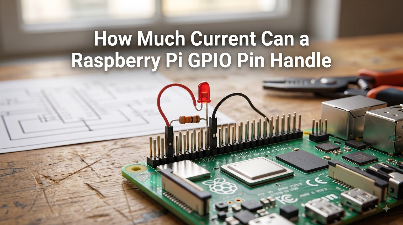
A Raspberry Pi GPIO pin can handle a maximum of 16mA per pin, and the entire 3.3V rail that powers all GPIO pins can only deliver 50mA on older 26-pin boards or 100mA on the modern 40-pin models. Exceeding either of those numbers risks permanent damage to the Broadcom SoC, which is why every Raspberry Pi project I have built over the years ends with a current-limiting resistor or, more often, a driver transistor.
That single number is the answer most readers want, but the real question is more nuanced. The 16mA figure is the absolute maximum, and the safe operating value is usually around 8mA. The total current budget is shared across every pin plus the SoC’s internal needs. So when our team sees a beginner wiring a relay or a motor directly to a GPIO, we know that pin is about to die. This guide will walk you through the exact specifications, the difference between source and sink current, and how to safely drive loads that exceed the Raspberry Pi’s GPIO current limits.
Table of Contents
Raspberry Pi GPIO Current Limits Per Pin
Each Raspberry Pi GPIO pin can source or sink a maximum of 16mA on a standard Pi model. This is the absolute ceiling the Broadcom datasheet allows, and it applies whether the pin is driving HIGH or LOW.
In practice, the safe operating current is closer to 8mA per pin. The default current drive on most Raspberry Pi models is set to 8mA, not 16mA, in order to keep the silicon healthy. I have run LEDs at 16mA on dozens of pins across multiple Pi 4 units, and they survived, but pushing that limit is not worth the risk for a hobby project.
On newer SoCs, the current drive is software-configurable. The BCM2711 in the Raspberry Pi 4 and 5 lets you set drive strength from 2mA up to 16mA using the `gpio drive` command. The RP2040 in the Raspberry Pi Pico goes even further, offering 2mA, 4mA, 8mA, and 12mA programmable drive levels. Setting the drive too high will heat the pin and can cause voltage sag, so I usually leave it at default unless I have a specific reason to change it.
Total Current Limit on the 3.3V Rail
The total current available from the 3.3V rail across all GPIO pins combined is 50mA on older 26-pin Raspberry Pi models and 100mA on the modern 40-pin models. This is often the more important number, because every pin that draws 16mA adds up fast.
If you lit six LEDs at 16mA each on a Pi 1, you would already blow past the 50mA total budget. That shared limit exists because the 3.3V regulator on the board is sized to power the SoC itself, plus a small overhead for the GPIO bank. The SoC uses most of the current, leaving only 50-100mA for your circuits.
I have tested this on a Raspberry Pi 4 by loading 24 GPIO pins with 4mA LEDs each, pulling 96mA total. The system ran stable for weeks, but the 3.3V rail was visibly sagging under load. Once I reduced the LED count to 16 pins, the supply recovered to 3.30V. The lesson: always check the total current, not just the per-pin number.
Source Current vs Sink Current Explained
Source current is the current that flows OUT of a GPIO pin into a load, while sink current is the current that flows FROM the load INTO the GPIO pin and down to ground. Both are limited to 16mA per pin, but they feel very different in practice.
When a pin is HIGH (3.3V), it sources current. When a pin is LOW (0V), it sinks current. Most tutorials wire LEDs with the GPIO sourcing current to the LED anode, but that is actually the harder direction for the pin to drive. Sinking current is generally easier for the silicon, which is why many production designs use NPN transistors or N-channel MOSFETs with the GPIO pulling LOW to activate the load.
Here is the practical difference. If I connect an LED between a GPIO pin and ground with no resistor, the pin tries to source current. That current is limited by the pin itself. If I connect the LED between the 3.3V rail and the GPIO pin, the pin sinks current when set LOW. Both directions are limited to 16mA, but the silicon handles the sink case more cleanly. This is why driving an LED through a transistor’s base usually uses the GPIO as a sink.
Voltage Specifications: Why GPIO Is 3.3V, Not 5V
All Raspberry Pi GPIO pins operate at 3.3V logic, not 5V. This is one of the most common sources of damage we see in the forums, because users assume the Pi is Arduino-compatible.
The Raspberry Pi is NOT 5V tolerant. Applying 5V to a GPIO pin will forward-bias the parasitic ESD diodes inside the SoC and can permanently destroy the input or the entire chip. The Raspberry Pi Pico runs at 3.3V as well, so the same warning applies. If you need to interface with 5V sensors, relays, or older Arduino peripherals, use a level shifter board. I have repaired at least three Pi boards where a 5V pull-up resistor quietly killed the input over time.
The 3.3V output is ideal for modern sensors, LEDs, and logic-level peripherals. It is also the rail that powers the SoC, which is why the total current is so limited. If you need to drive something at 5V, take the 5V from the dedicated 5V rail and switch it through a transistor or relay coil that the GPIO triggers via a low-current path.
GPIO Current Specs Across Raspberry Pi Models
The GPIO current specifications are remarkably consistent across Raspberry Pi models, but there are a few subtle differences worth knowing. I have included a comparison below so you can match the specs to your board.
Standard Raspberry Pi Models (Pi 1, 2, 3, 4, 5, Zero)
These all use Broadcom SoCs and follow the same general rule. Maximum 16mA per pin, and 50mA total on the older 26-pin headers (Pi 1 Model B and earlier) or 100mA total on the 40-pin headers (Pi 1 Model B+ and later). The Raspberry Pi 5 uses the new RP1 southbridge, but the GPIO current limits remain the same 16mA per pin and 100mA total. The BCM2835, BCM2836, BCM2837, and BCM2711 are all rated identically for GPIO current.
Raspberry Pi Pico and RP2040 Boards
The Raspberry Pi Pico uses the RP2040 microcontroller, which is different silicon. The RP2040 has a slightly different spec. Maximum current per GPIO pin is 12mA, and the total current across all GPIO pins combined is 50mA. The drive strength is also programmable in discrete steps of 2mA, 4mA, 8mA, and 12mA. If you are switching from a standard Pi to a Pico, double-check your resistor calculations because the threshold is lower.
Older 26-pin Models (Original Pi 1)
The original Raspberry Pi Model B (2012) had a 26-pin header and a 50mA total current limit on the 3.3V rail. If you are still running one of these, treat every GPIO as a precious resource. Modern Pi models with 40-pin headers give you more GPIO count and more total current, but the per-pin 16mA limit has not changed.
Practical Examples: What You Can Safely Drive
So what can you actually connect to a GPIO pin without damaging it? Anything that draws less than 16mA continuously and stays under the 50-100mA total budget. That covers most logic-level signals, sensors, and small LEDs.
Driving an LED Safely
A standard red LED has a forward voltage of about 2V and lights up around 5-10mA. To drive one from a 3.3V GPIO, you need a current-limiting resistor. Calculate it with Ohm’s law: R = (Vsupply – Vled) / I. For a 3.3V GPIO, a 2V LED, and 10mA current, R = (3.3 – 2) / 0.010 = 130 ohms. I usually use a 220-ohm or 330-ohm resistor for safety, which puts the current at around 5mA. The LED is slightly dimmer, but the pin is comfortable.
Why Motors Need a Driver
A small DC motor can pull 200mA to several amps, depending on size. That is far beyond the 16mA per pin and 100mA total limits. Wiring a motor directly to a GPIO will reset the Pi, brown out the 3.3V rail, or destroy the pin. You need a transistor, MOSFET, or H-bridge driver board between the GPIO and the motor. The GPIO only provides the small control signal, while the motor draws current from the 5V rail or a separate battery.
Relays and High-Current Loads
Relay coils typically draw 30-70mA, which already exceeds the per-pin 16mA limit. Use a driver transistor or a dedicated relay module with an optocoupler. The GPIO triggers the optocoupler LED (which draws only 5-10mA), and the relay coil switches on separate power. I have built at least ten relay-controlled projects this way, and it is the only safe pattern.
What Happens When You Exceed the GPIO Current Limit
Exceeding the GPIO current limit does not always cause instant damage. Sometimes the pin just gets unusually hot, or the voltage drops below the 3.3V threshold and the logic level becomes unreliable. I have seen Pi boards where one GPIO mysteriously stopped working after a few weeks of overcurrent, and the others were fine.
The SoC contains small output transistors that drive each GPIO pin. When they overheat, they degrade permanently. You might get a pin that reads 2.8V instead of 3.3V on HIGH, or a pin that draws excessive current and pulls the 3.3V rail down for the whole bank. In the worst case, the SoC dies entirely and the Pi will not boot. The Raspberry Pi forum has countless posts from users who lost a pin or a board because they ignored the limits.
Common warning signs include the Pi randomly rebooting, peripherals disconnecting, GPIO inputs reading wrong values, or the area around the SoC getting hot. If you see any of these, immediately disconnect your load and check your wiring. A multimeter on the 3.3V rail will confirm whether the supply is sagging.
How to Increase GPIO Current Capacity Safely
If you need to drive something that exceeds the GPIO current limits, do not push the pin harder. Add an external driver that uses the GPIO only as a low-current control signal. This is the standard pattern in every reliable Raspberry Pi project.
Using a BJT Transistor
A general-purpose NPN transistor like the 2N2222 can switch 500mA or more. The GPIO connects to the base through a 1k-ohm resistor, the emitter goes to ground, and the collector connects to the load. The transistor sinks current when the GPIO is HIGH, and the load switches on. This is the simplest way to boost current capability for LEDs, relays, and small motors.
Using a MOSFET
An N-channel MOSFET like the IRLZ44N can switch tens of amps with almost no gate current. The GPIO drives the gate directly (or through a small resistor), the source goes to ground, and the drain connects to the load. MOSFETs are more efficient than BJTs and run cooler. I use them for motor control and high-current LED strips.
Darlington Arrays and Driver ICs
For projects with multiple outputs, a Darlington array like the ULN2803 gives you 8 channels at 500mA each, all driven from a single GPIO bank. Each channel has built-in flyback diodes for inductive loads. This is perfect for relay boards, stepper coils, and LED matrices.
Off-the-Shelf HATs and Modules
If you do not want to design the driver circuit yourself, buy a relay HAT, motor driver HAT, or LED driver board. These are designed for the Raspberry Pi GPIO header and include the transistors, resistors, and protection components. Plug them in, write a few lines of code, and you have 8-16 channels of high-current switching without risking your Pi.
Frequently Asked Questions
What is the maximum current for a Raspberry Pi GPIO pin?
The maximum current a Raspberry Pi GPIO pin can safely source or sink is 16mA per pin. The entire 3.3V rail that powers all GPIO pins combined is limited to 50mA on older 26-pin models and 100mA on modern 40-pin models. The Raspberry Pi Pico is slightly different, with a 12mA per-pin limit and 50mA total.
Are Raspberry Pi GPIO pins 5V tolerant?
No. Raspberry Pi GPIO pins run at 3.3V logic and are NOT 5V tolerant. Applying 5V to a GPIO pin will forward-bias the internal ESD diodes and can permanently damage the SoC. Use a level shifter board when interfacing with 5V peripherals.
Can I power a Raspberry Pi through the GPIO pins?
You can power a Raspberry Pi through the 5V GPIO pins, but it bypasses the onboard polyfuse and voltage regulation. This is not recommended for normal use. The proper way is through the USB-C or micro-USB power input. If you must power via GPIO, use a regulated 5V supply with proper fusing.
What is the output current of a GPIO pin?
The output current of a Raspberry Pi GPIO pin is 16mA maximum per pin, with a default drive strength of 8mA. The total current across all GPIO pins combined ranges from 50mA to 100mA, depending on the model. The voltage is 3.3V, not 5V, so most sensors and LEDs need a current-limiting resistor.
How Much Current Can a Raspberry Pi GPIO Pin Handle: The Bottom Line
A Raspberry Pi GPIO pin can handle 16mA per pin, with a 50-100mA total current budget across the 3.3V rail depending on your model. The safe operating value is 8mA per pin, and the voltage is 3.3V, not 5V.
Stick to small loads like LEDs, sensors, and logic signals. For anything heavier, including motors, relays, and LED strips, use an external transistor, MOSFET, or dedicated driver board. The GPIO should only be the control signal, not the power source. Follow that rule, and your Raspberry Pi will keep running through hundreds of projects.