As systems and processes we develop are increasingly complex the amount of possible interactions can reach levels hardly imaginable only a couple of decades ago, thus requiring careful testing and documentation in order to avoid unpredictable behavior. The amount of computing power we have at our disposal nowadays allows us to simulate and analyze even the most complicated processes before implementing them in the real world.
A short while back I had the opportunity to review the Visual Components advanced simulation software which represents a complete solution for designing and optimizing production line layouts. Professionals can simulate the entire production process complete with material flow, robotics and equipment setup, generate detailed reports and analyses and quickly change and customize process flow according to requirements.
Overview
Visual Components was founded in 1999 as a partnership between Finnish and American simulation experts. The first product to be released was 3DRealize back in 2000, which was the first of its kind capable of simulating robotics equipment and material flow on the same platform.
Fast forward to present day Visual Components offers a line of products with a wide range of applications in industrial environments. Product manufacturers can design and simulate production lines or even entire factories much faster with greatly reduced costs, while retooling existing production facilities can become a breeze.
Almost every aspect of the production process can be simulated, including material flow, machinery and robotics operation, support for offline programming enables designers their programs before uploading them to the actual robots, while open-source COM and Python APIs extend versatility by allowing creation of custom presentation and development solutions.
The component library is huge comprising over 1800 3D models for various hardware including machinery, conveyors, part feeders, tools, factory and building facilities, countless accessories, packaging, complete simulations and of course robots from over 30 manufacturers such as ABB, Fanuc, KUKA, Mitsubishi, Panasonic and more.
Getting started
Most modern computers running Windows 7 or a newer edition OS, either 32-bit or 64-bit editions, should have no trouble coping with the hardware requirements of Visual Components products. Also an Internet connection is required for licensing and accessing the extensive online component library.
The current product lineup consists of 5 software packages that offer various feature sets and serve different purposes.
3DAutomate introduced in 2012 and taglined as the flagship product of the company, this software can be used to simulate entire factories being well suited for production facilities of automotive manufacturers.
3DCreate allows designers to create accurate simulations of production lines either by using component library models or by importing external CAD files. The software offers the complete set of features required to customize models, workspaces, programming and so forth. COM and Python APIs are also available for further customization of projects.
3DRealize is the entry level tool that offers all basic functionality required to quickly set up a production line using 3D models from the library, visualize the behavior of various equipment or perform on-the-fly changes to the solution. This can be a great tool for more interactive presentations.
3DRealize R is similar to the previous but offers more editing and analytical features and allows users to apply changes to 3D models.
3DSimulate Comes with more extensive analysis, statistics and reporting features and also offers an API for more customized presentations.
The help section within the software is well structured and easy to understand and it also includes extensive documentation for Python. Online help resources are also available, including video tutorials and detailed documentation, and the online community is also well established.
Basic usage scenarios
In the following I tried to cover a few basic usage scenarios to point out some features the software offers. For the examples below I have used 3DCreate to access all functionality.
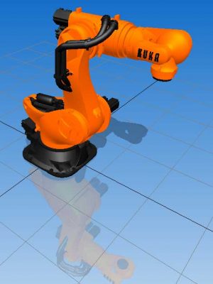
Creating robot motion is fairly straightforward thanks to the intuitive interface of Visual Components and the extensive help video and written documentation available. From the eCat library tab a model is selected and dragged onto the working surface. From there we switch to the Teach tab where the robot’s motions can be set up. The Jog offers options on how to position the robot – rotate about its joints or translate and rotate with respect to the end effector. The robot can also be positioned by using numerical values in the Param tab. After a few minutes of tinkering I could create a sequence of point-to-point motions as shown below.
Every element and aspect of the simulation can be customized. In the robot arm simulation above when we switch to the Create tab all model attributes can be accessed and customized – textures, colors, shape and size, configuration, inputs and outputs, robot controller response, kinematics and so much more. Python scripts can also be used to customize desired aspects of the simulated model.

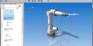
Creating a basic routine is also a very intuitive and, dare I say, pretty fun process. For this purpose two conveyor belts and one parts feeder are added to the simulation. The PnP button from the function toolbar is pressed and then the robot is selected. Afterwards the Connect Signals from the interactive toolbar just above the work area needs to be pressed to open the Connection Editor which allows mapping I/O signals of the robotic arm. With this procedure complete we return to the Teach tab where robot positions and actions are defined to complete the process.
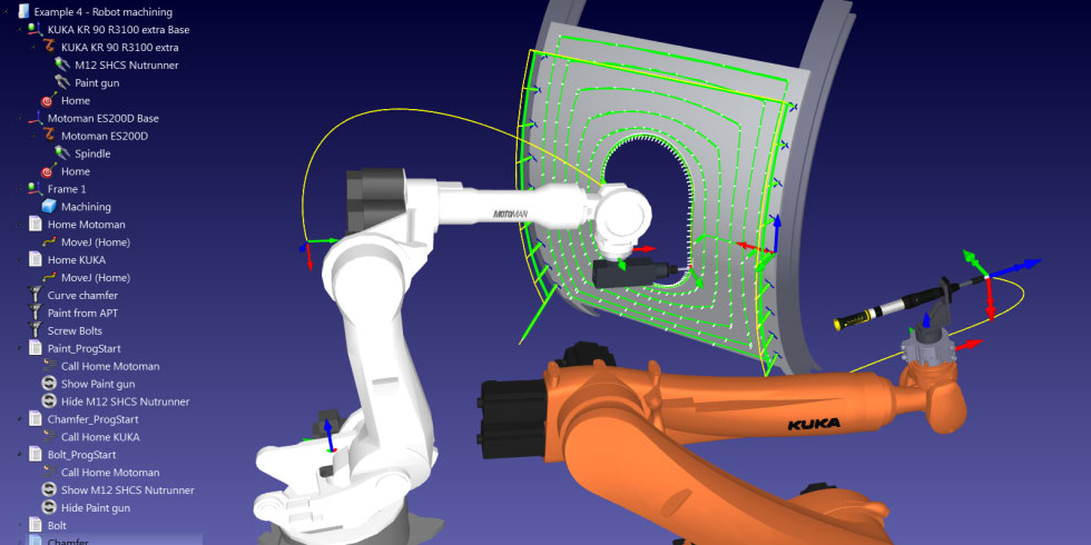
Demo layouts from the component library can showcase how powerful the software can be. Below is a more complex example which includes a human operator that places a workpiece on the positioner for the robot to work on.

Head to the product page for more information and licensing. Also please check back regularly as more practical examples will be added soon.