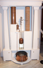
Since ancient times man has imagined automated mechanisms or intelligent devices to take over various activities or parts of his work, in the timeless quest to make life easier, more comfortable and achieve goals not possible otherwise. Automatic control systems (ACS) have a very long history, it is arguably considered that the first such system appeared around the third century B.C. in the form of Ktesibios’s water clock and numerous other examples of such automatic devices being recorded throughout history in different periods of time.
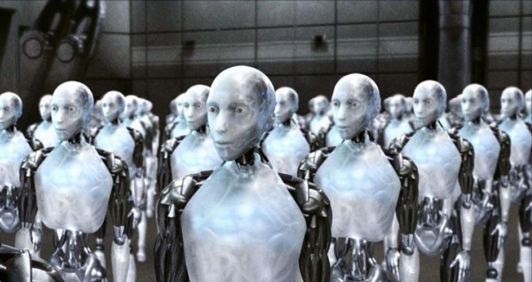
The concept of robot is somewhat younger, only 500 years old and can be traced back to the days of Leonardo da Vinci, his work containing numerous depictions of automated mechanisms or even robotic structures. The actual term surfaced in 1920, when Czech writer Karel Capek published the play R.U.R., short for Rossum’s Universal Robots.

Etymology of the word robot has Slavic origins, with meanings equivalent to work or chore in the Russian and Czech language respectively. American science-fiction author Isaac Asimov made the term more mainstream and also foresaw the electronic brain that controls a robot. He also devised the Three Laws of Robtics.
A robot is, par excellence, an automatic control system that comprises a collection of subsystems, each of them controlled by one or more processing units that are programmed with algorithms to handle specific purposes, a definition accepted by the International Standards Organization (ISO) and other institutions, more information about standards can be found in our dedicated article.
[yellow_box]Head to our dedicated article about robot definitions and industrial standards[/yellow_box]
Classification of automatic systems
There are various criteria by which automatic systems can be classified. These are:
- Type of external I/O parameters:
- Deterministic systems – external variables are deterministic, meaning that each parameter has an unique value at a certain operating mode of the automated system and at a certain moment in time;
- Stochastic (random) systems – at least one of the external variables is has random values, assuming the same operating mode of the automated system at the same moment in time;
- Number of external parameters (variables):
- Single input and output (SISO);
- Multiple input and single output (MISO);
- Multiple input and output (MIMO);
- Control principles:
- Open loop control – no information is gathered from external disturbances or system output, commands are issued in a predefined manner;
- Feed-forward control – designed to compensate for external disturbances influencing the system when calculating commands;
- Feedback control or closed loop control – system output is monitored and commands are calculated accordingly;
- Combined control – disturbances and system output are monitored when issuing commands;
- Type of system parameters:
- Continuous or analog systems – variables consist of continuous signals with an infinite array of values;
- Discrete or digital systems – variables are of certain certain values or consist of discrete sequences of impulses sampled by means of analog-to-digital conversion mechanisms;
- Variation characteristic of the input:
- Automatic stabilization systems – input parameter value is constant for a certain operating mode and is known beforehand (reference);
- Input following systems – input parameter is variable and known beforehand;
- Systems with programmed regulation – input parameter varies according to a predefined variation law;
- Type of governing differential equation:
- Linear systems – variation characteristics are linear, i.e. proportional to each other;
- Non-linear systems – they do not have proportional output to input responses.
System types explained
Automatic stabilization systems must maintain constant the value of the regulated parameter, with a certain imposed precision, determined by the variation range of external disturbances influencing the system. In such systems the input the reference which is constant at a certain operating mode. Input and output signals may be of different nature.
Input following systems must ensure that the variation of the regulated parameter reproduces, with certain precision, the variation characteristic of the input parameter. The input parameter variation law is not known beforehand. We must note that there are no important differences in the operating principle of stabilization and input following systems, the only difference is the variation characteristic of the control signal.
Systems with programmed regulation must ensure the variation of the regulated parameter according to a predefined pattern that determines the input. The systems are actually a special case of input following systems, with the only difference that the input variation characteristic is known beforehand.
Extremum seeking systems are designed to keep their operating mode at an extremum value, either minimum or maximum, of a function that governs the system defining certain a certain index or indexes – e.g. performance, quality, efficiency, etc. This function can be dependent to either a single variable or multiple variables, which consist of the system’s operating parameters.
Such systems are different to standard regulation systems in the way that the extremum value must be computed or sought permanently, and then the adjustment or tuning of the system must be accomplished. Seeking the extremum is a basic operation that is unique to this type of systems while tuning is equivalent to error suppression mechanisms in regular automatic systems, and because of these attributes they are also called automatic tuning systems. The seeking and tuning operations must take place because extremum functions are non-univocal, therefore it is not known beforehand if the current operating mode is above or below an extremum. Such systems employ closed-loop control because the actual output of the system is measured and taken into account.
Optimal control systems take into account not only current values of various parameters, as in extremum seeking systems, but also their time variation characteristics, employing functions and their derivatives to define relationships between variables. Complex mathematical models, dynamical programming and other techniques are required to accomplish this type of control hence a certain amount of processing power is implemented in control units of such systems.
Adaptive systems are designed to continuously monitor and take into account external disturbances acting upon them. Such disturbances can alter the operation of a system o a great extent and can drive internal parameters outside predefined limits, generating important regulation errors and can even completely disable the system. Therefore such a system must be able to alter its internal parameters and sometimes even its structure to keep its output close to predefined internal models or algorithms.
Adaptive systems are able to asses performance on their own by measuring internal state variables, output or by calculating various performance indexes, making decisions by comparing references to actual parameters and performing alterations in parameters in structure based on their decisions.
Systems control principles
Open loop control does not take into account any external parameter. Internal algorithms of a system handle all control tasks and relevant functionalities must be foreseen and implemented.

In the diagram above we have the Process with an output y(t), an input i(t) and a disturbance f(t). The system input is generated by a generic Transducer, which can be replaced by a routine or a program, and is sent to the Control device. This device, which handles all signal conversion tasks, generates the control signal u(t) which is sent to the Execution element which performs a physical task m(t) in the Process. We can see that no external parameters or outputs are measured, the accuracy of the system relies solely on construction.
Feed forward control is employed when a system is subjected to important external disturbances and predefined functionalities cannot be carried out with a certain amount of precision. In this case external disturbances are measured and taken into account when computing commands, compensating for their effects upon the system.

In this diagram we have a Measuring device which monitors disturbance f(t) and sends information u2(t) to the Algebraic summator which adds it to u1(t) generated by the Control device and generating command u(t)which takes into account not only the default response of the system but also the value of the disturbance.
A disadvantage of this type of control is that not all types of disturbances influencing a system can be taken into account, therefore in time errors in operation will appear at a certain moment. This control principle is employed in combined control systems, together with feedback control to enhance the precision of the latter.
Closed loop or feedback control takes into account the actual output of the system when generating commands. A feedback control system will remain stationary unless differences between the actual output and this reference occur. These differences can be caused by external disturbances, case in which they are errors, or when the reference of the system is changed. When this happens the system will enter a transient phase generating commands to reestablish equality between the output and the reference. Commands can be either equal to the difference between the reference and the output or greater, to overcompensate for the difference according to a certain model or algorithm effectively improving the response time of the system.

In this type of control a Feedback transducer is employed which measures the Process output y(t) converts it and sends the information r(t) to the Comparator. The device compares input i(t) and r(t) and generates the response ε(t) which represents the error of the system. If there is no difference between the input and the output of the system then m(t) will be constant.
Components of an automatic control system in a robot
If we refer to the feedback control diagram above we can imagine an analogous automatic system found in a robot. Such system is comprised of:
- The mechanical action as the process to be controlled;
- Disturbance influencing the dynamical system;
- The actuator which is the execution element acting upon the process;
- The mechanical system which is comprised by the actuator and the mechanical device that performs an action;
- The controller which is the control device calculating and generating control signals;
- The sensor which is the feedback transducer measuring the output of the system;
- Input (reference) signal;
- A filter for converting the input (reference) into appropriate signals for the controller to interpret;
- The comparator which determines the difference between the reference and the output;
- And the control signal which is sent to the actuator in order to achieve a certain response from the system.
Resources
- Control theory article, Wikipedia
- Automation article, Wikipedia
- Open loop and closed loop control, Ruhr University Bochum
- “Adaptive Extremum Seeking Control of Nonlinear Dynamic Systems with Parametric Uncertainties” by M. Guay and T. Zhang
- Ktesibios of Alexandria – history article, Hellenica.de