This summer brings us the new Visual Components Essentials which is set to replace the current lineup of factory design and simulation products. The workflow has been completely redesigned with speed and simplicity in mind, complemented by new features such as automatic 2D drawing and bill of materials generation, new export formats and more. The software aims to be a complete tool not only from an engineering standpoint but also for marketing and sales purposes, being able to generate accurate and meaningful presentations.
There are a lot of changes under the hood as well, the simulation engine takes advantage of the latest hardware technologies for an increased level of realism, while the new open architecture and API make it easy for developers to create custom applications based on the Visual Components engine.
Overview
Showcased last week at the Automatica Fair held in Munich, Germany the new Visual Components Essentials software suite sports a completely redesigned work environment with all functionality is grouped into four large sections, based on the type of supported activity or task. Contextual menus further enhance the experience by exposing the most common actions at a certain point to the user.
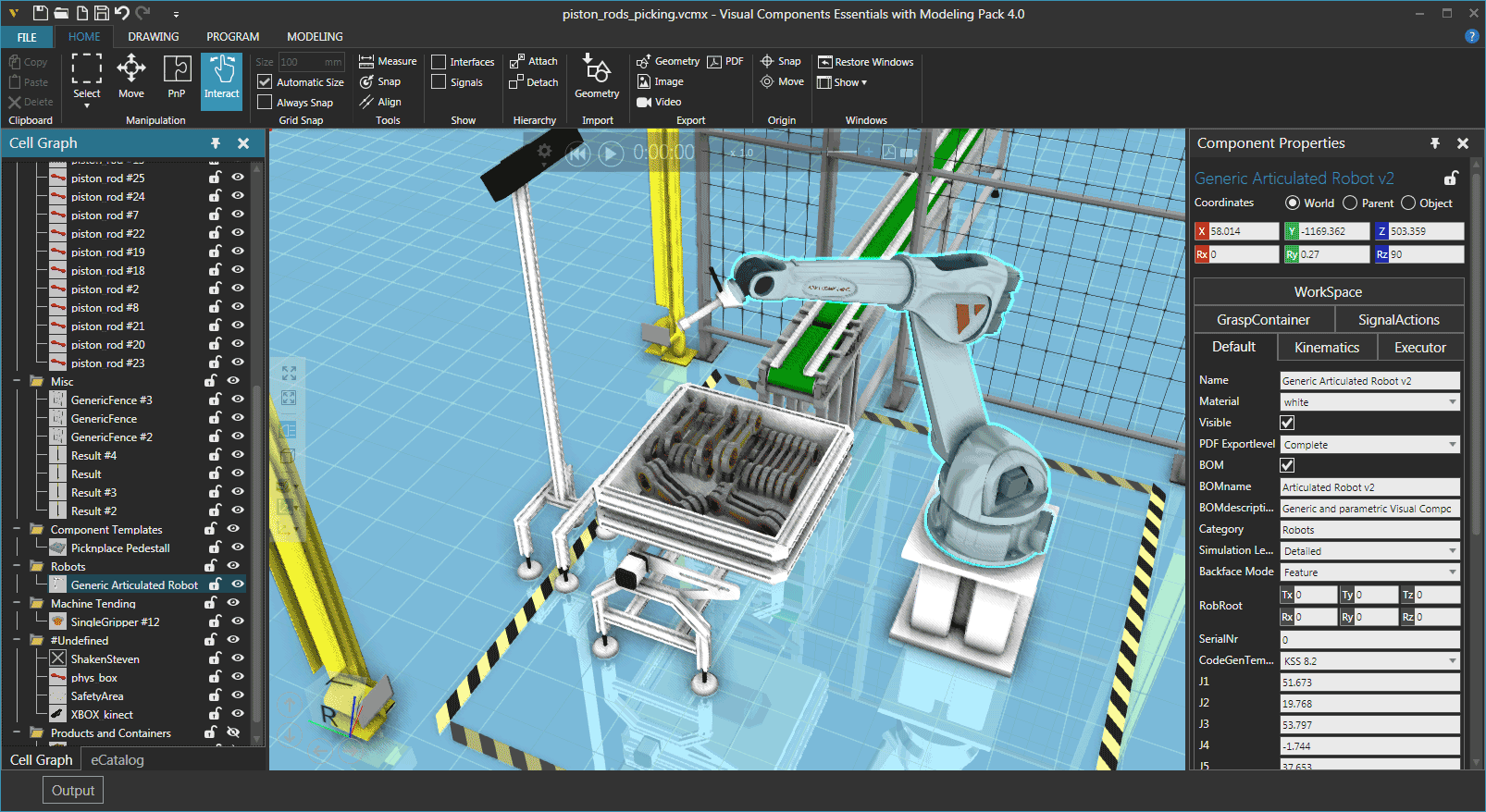
Home is of course the main work screen where most of the things for setting up the simulation will take place. Here the user can select and add geometries to the layout, as well as edit their attributes and positions. The eCatalog contains thousands of 3D models of robots, tools, accessories and other equipment from all major manufacturers, as well as complete functional layouts ready to be imported. Export features for video, 3D PDF or vector graphics can also be accessed from here, along with other common features.
Drawing is the section dedicated to 2D drawings. These are generated directly from the 3D rendering, and can be edited as required. A bill of materials (BOM) is also generated and added to the drawing. It can be printed right away or exported to standard PDF, DWG or DXF formats to be further edited if needed.

Program exposes functionality required to create routines for the robots to follow throughout the simulation. Here all the signals and interfaces available for a certain robot or equipment can be accessed and configured. I have added a simple example of working with signals later in the article.

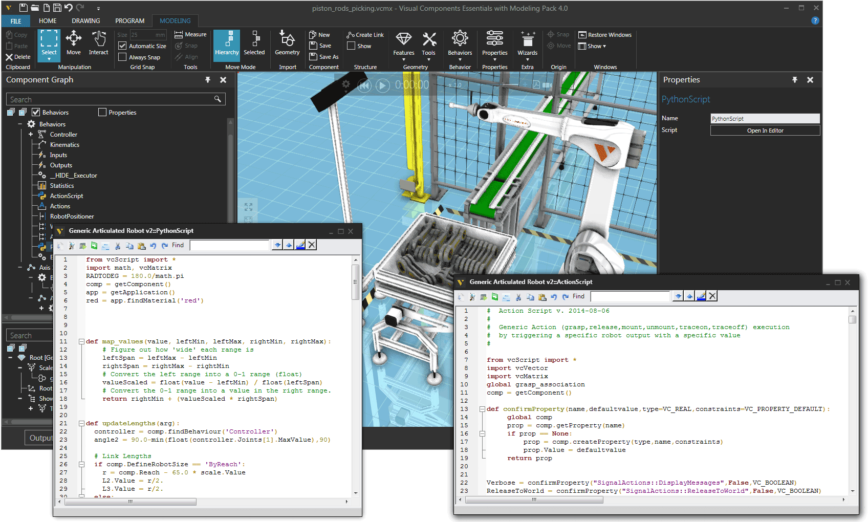
Modeling this section is dedicated to advanced customization of all the elements in the simulation. The user can alter geometries, modify kinematics parameters of joints, define custom actions or signals, and essentially alter the behavior of robots or other equipment present in the layout to virtually any extent.

An integrated editor lets the user access and modify scripts for a certain robot.
New features
As mentioned earlier the VC Essentials offers not only interesting new features but lots of enhancements as well. Playback and 3D navigation controls are now always visible in the simulation area, letting the user review program steps on the fly. The 3D rendering menu allows for quickly changing the visualization type even while the simulation is running.
The navigation controls are also accessible while recording video, making it possible to add some interesting panning and zooming effects to presentations. Every object in the workspace is interactive and contributes to the simulation, making it possible to attain pretty high levels of realism.
Examples
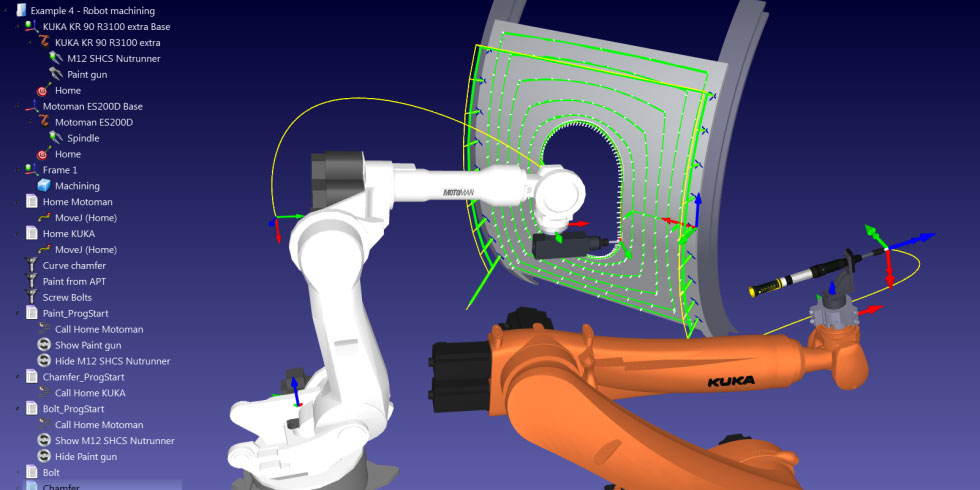
For the example below I used two robots, a generic Visual Components geometry and a heavy duty KUKA KR 1000 L750 Titan F which mirrors movements of the first robot. Naturally it will take longer for the KUKA robot to perform a movement since it is larger and much more heavier than the first one. To synchronize movements I used signals to enable the VC robot to wait after it reaches a certain point for the other robot to complete the similar movement.
The second simulation is based on a pick and place imported layout in which a generic VC robot picks up piston rods from a bin using a vacuum gripper, and places these on a conveyor belt. The sensor on the left monitors the bin and triggers it to shake if no piece is in a favorable position to be picked up.
Hopefully you have found my review useful. For more information head to the product page and please check back regularly for more updates.